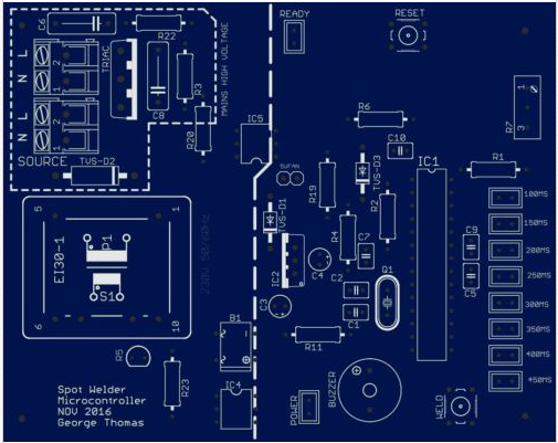
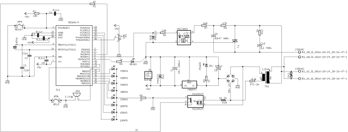
The ATmega328 based Spot Welder Microcontroller
Earlier when i did mini projects it was hard to solder the 18650 batteries that i had salvaged from old laptops. Not recommended by the manufacturers either. not all the cells in a laptop battery pack were bad, so why not take them out and make use of them to power some DIY stuffs like a power bank for example. They cost a lot when purchasing new ones from online stores. So the best way electrically connect them was to spot weld them using nickel strips.
One way to get it done is to salvage an old Microwave Oven Transformer (MOT) and modify it to get approximately 400 to 600amps (the turns ratio is something you’ll have to figure out). Here the current has to be kept low. Generally reducing the voltage will also reduce the current here. I’ve used 3 turns at secondary with 10mm width flexible cable. That would give enough amps to weld. I’ve set the weld time from the pot to 60ms.
NOTE:
- More turns with thicker cable would give more current
- Less turns would decrease current.
The components used here are cheapest those that are readily available at any local store.Then comes a Microcontroller built on the ATMEL ATmega328 chip. This controls how long the weld is done. The weld time are measured in milliseconds. When spot welding it is common as well as important that there be two welds, Why ? because the first weld clears the strip of all impurities that maybe stuck to it after production. The Second weld is when the strips melt and gets welded to the cell. The chip is powered by a regulated 5v supply from an on-board PCB transformer.
Features:
- Surge Protection
- Inbuilt Power Supply
- Dual Pulse Welding
- Dual Surge protection
- Thermal fuse at the secondary
- Zero Cross Peak detection
- Variable timed pulse (indicated by LED from 100ms to 450ms)
- Dual function weld
- Manual Weld
- Continuous Weld (upon holding weld button for more than 800ms)
- TVS protection diode at the dc side
- Snubber Circuit
- TRIAC to control AC load
- Audible Weld alert
Working:
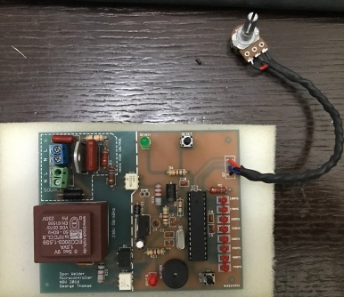
The Spot Welder Microcontroller is powered by a PCB transformer rated 2 x 9v 177mA. The PCB is protected by a TVS diode D13. This protects all the underlying components from surge without which would burn the components during a surge such as lightning. here the TVS diode suppress the spike in voltage when the threshold voltage is reached.
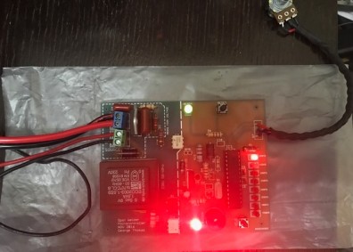
Once switched on all the timing LEDs blinks once. The READY led indicates that it is ready for welding. The ATmega gets its clean power from the regulator IC LM7805 filtered by capacitors C9, C7 and C5. The ATmega continuously monitors the AC zero crossing signal from the Optoisolator H11AA1. The optoisolator sends out a pulse for every zero crossing of the AC signal and when the weld button is press, the ATmega sends out dual pulse to another optocoupler triggering the gate of the TRIAC BTA26.
The first Pulse duration is 500ms which prepares the tab for welding, the second pulse is when the actual weld happens. The TRIAC by nature switch’s off at every zero cross. Here a little late after zero crossing but that would not make a difference as it a few micro seconds. Since the load will be an MOT and thus highly inductive, it is very important that load is switched ON at the peak of the sine wave and not at zero. When the Weld button is pressed and held down for a period of 800ms, this helps when you have to weld several cells at a time to built a battery pack. The TRIAC conducts 6 times with a two second delay between each weld. The LEDs 50ms to 120ms reflects the value set by the potentiometer.
Working video can be viewed here.
Scope View
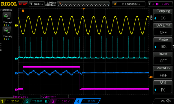
The above scope shows the following, respective to the numbers
- AC reference voltage (YELLOW)
- Zero Crossing ( LIGHT BLUE)
- Second pulse send from the Arduino to trigger the TRIAC ( PURPLE)
- Secondary wave from the MOT (BLUE)
With a little modification or as a complete replacement, this pcb can used for the cheap Chinese Models like the SUNKO 788H

Sunko 708A Replacement:
One of the readers Giordano Cantori had been very nice to send me the pictures of his finished Sunko 708A Spot Welder after the stock board had failed. He had replaced it with the PCB described here with his own idea and design.


Here is the built in action
To upload the firmware you would need
- Download Xloader. The Website to Xloader is here.
- Download the required firmware here. Choose the 10 to 80ms timing firmware or the 100 to 450ms.
To upload, its very simple and straight forward. From xloader browse to the new firmware
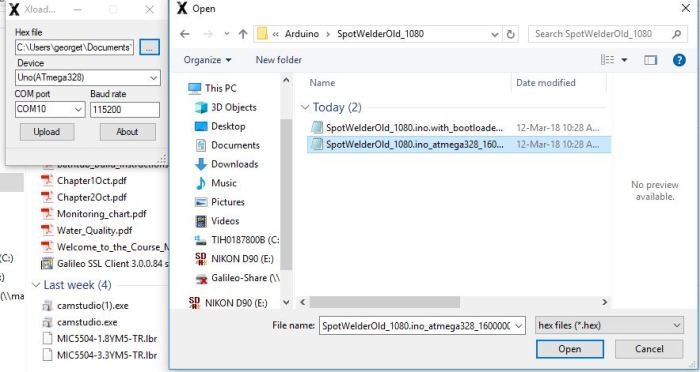
Next make sure you have arduino installed and the correct port number is selected in Xloader. Then click Upload. That is it.

how to adjust the current ?
LikeLike
It’s time that is adjusted not current.
LikeLike
Thanks for sharing this design. Your welds look beautiful.
You write the first pulse duration is 500ms, that seems long, is that correct?
Also, how much pause you you use between first and second pulse?
LikeLike
That’s correct is way too much. Could have been a typo.
20 to 40 seems to be perfect and delay of 100ms would be fine before the second pulse. The idea is on the first pulse the joint should not glow or form a nugget but just hot. You could do some test pulse and get a sweet spot. Secondly quality of the weld depends on the electrode also. An oval or round tip is better than a sharp one.
Hope this helps.
LikeLike
Try now. This should work. Don’t have the assembled board at the moment so I am just relying on your feedback.
LikeLike
Hi George,
Where I could find the original firmware with timing from 100ms and up. I was working with times up to 80ms, but I find out that it doesn’t perform well when having multilayer weld (when joining cell groups together). So I believe 100ms and up should work better here.
Thanks!
Gediminas
LikeLike
Which version do you have ? 1 or 2.0 ? The one with a display or without it ?
LikeLike
Thanks for a quick reply!
The first one.
LikeLike
I suggest you keep IC. one with current configuration and the other. What timing do you need for the second ?
LikeLike
I think it could be the original one from 100ms to 450ms. Later I will find out which timing works best.
LikeLike
Will share it in a while.
LikeLike
you can download it now. I’ve added one more firmware with timing profile as follows, 100, 150, 200, 250, 300, 350, 400, 450.
LikeLike
Thanks! Something is wrong with that version as it doesn’t react to a potentiometer. I have rolled back to previous version 10-80ms and it does react, but not this one which you have uploaded. Any ideas?
LikeLike
Try now.
LikeLike
According to the file size, the file did change, but the behaviour is still the same. Sticks to 450ms and doesn’t react to the potentiometer.
LikeLike
You mean it stays at 450ms and does not respond to the pot ????
LikeLike
that’s right
LikeLike
it works now, thanks!
LikeLike
Excellent.
LikeLike
Hi,
Maybe you will have an idea what is wrong with my welder. After doing around 20 welds welder power decreases and it stops welding. After an hour I can do another 2-3 weld, but basically, it restores just the next day. That’s not something new with my welder it just got more annoying now as I use it more often.
Any ideas are welcome. Thanks!
LikeLike
Can you check if anything is getting hot. Seems like to me the TRIAC is. Take a temp reading when the welding power goes low as you say.
LikeLike
It could be transformer as well, if it gets hot then there is resistance within the wire.
LikeLike
Just checked with a thermal camera. Nothing except atmega and something around B1 gets warm. But their temperature goes just up to 31 degrees. So, I think it’s fine. I have checked my first batteries and find out, that my first batteries got much better weldings comparing with the last battery and the result which I have now. So, I believe it’s degrading over time.
Any other ideas what to check?
LikeLike
I assume that is the ambient temperature within the enclosure. I don’t see any reason anything on the PCB would get hot.
Do several welds and check if the transformer is getting hot and add a fan inside the enclosure.
LikeLike
I think so too. I’ll back after I’ll have results after some weldings
LikeLike
Ok. Do let me know.
LikeLike
OK, I findout the problem – dirty pins 🙂
Thank you a lot for your help!
LikeLike
Always a pleasure.
There is something new to learn everyday. 👍🏻
LikeLike
Just curious, what pins ?
LikeLike
Welding pins. The ones which touch the nickel plate to weld. At some points, I have soldered wires and if flux gets somewhere near the welding point, it sticks to the pins degrading the resistance and my welder stops performing.
LikeLike
Ah ok. Glad all is well and working now.
LikeLike
poner pines ó electrodos de tugsteno de 2,6 mm, aguantan mas soldaduras.
El mié., 19 sept. 2018 a las 7:46, George Hobby () escribió:
> georgehobby commented: “Ah ok. Glad all is well and working now. ” >
LikeLike
Hi,
I saw your video here https://www.youtube.com/watch?v=pzZ7OPtYd2c and some samples pictures above, where 50ms impulses were used. Is there sketch update or something, where I could get that configuration of impulses? 100ms impulses makes almost burns on my welder. Thanks!
Gediminas
LikeLike
what configuration do wish to set ? You should start with 10ms. That is the smallest.
LikeLike
Thanks for a quick reply. I think that configuration would be good:
10, 30, 50, 60, 70, 80, 90, 100
LikeLike
Do you have the pcb ?
LikeLike
There is version 2.0 also. It has better control on the weld timing.
LikeLike
I have PCB, which is dated “NOV 2016”. I believe it’s v1.0? Does v2.0 firmware is compatible with v1.0 PCB?
LikeLike
The firmware are not backward compatible. To address your issue, the timing is actually multiples of 10. Which goes like this 10, 20, 30, 40, 50, 60, 70, 80. That image was send to me by one of my customers and he had set it up like that. The default weld timing i send out is as above.
LikeLike
Let’s try it. Could you please send me a firmware for a such configuration?
LikeLike
I have update the blog with the steps to download and upload the firmware. Let me know.
LikeLike
Thanks a lot. This configuration works much better for me.
LikeLike
Glad it does.
LikeLike
Nice design bro . Can u please provide me your code .
Thanks in advance
LikeLike
Thank you jrooprai. Unfortunately the code is not for the public.
LikeLike
As soon as the 220V is switched on, after the initial check, it goes immediately to continuous mode. In this condition if I use the mobile pliers I can weld a strip.
LikeLike
I guess its all ok now. 🙂
LikeLike
TRAIC failure can occur due to continuous use or underrated for the transformer your using. Does the TRIAC get hot during usage ?
LikeLike
The triac and the transformer are working. However, welding is performed.
LikeLike
Welding is performed ? So when does it continuously weld ? When pressing the button ? Or as soon the mains is powered on.
LikeLike
Hi George. I have a problem. As soon as it is lit, the welding machine goes into continuous solder mode.
LikeLike
Check the TRIAC. Giordano, that transformer, is it the one that came with sunko ?
LikeLike
OK! Thanks for the clarification!
LikeLike
It was not the PCB that was inverted, it was the schematic of the buzzer. Did not notice unless it came from the fab house.
LikeLike
Screenprinting on the pcb is inverted
LikeLike
Very good George! I inverted the buzzer connections. Now it all works wonderfully. Really a great job.
LikeLike
Glad it’s working now.
LikeLike
Sorry… I replaced the buzzer but it does not work. To try I also put a buzzer without internal oscillator. In this case you hear a tiny “clickc”. This means the signal is there?
LikeLike
I’ve been telling to check the polarity of the buzzer on the PCB.
LikeLike
Ho sostituito il buzzer ma non funziona. Per provare ho messo anche un buzzer senza oscillatore interno. In questo caso si sente un piccolissimo ” clickc ” . Questo vuol dire che il segnale c’è.
LikeLike
The + of the buzzer should go the opposite terminal on the PCB that is + of the buzzer goes to the Negative rail on the PCB.
LikeLike
Tracks are OK!
LikeLike
then i guess you may have placed the buzzer the wrong way. Can you send me the picture of the pcb, solder side and component side.
LikeLike
also check the trace to see if you can get a continuity on the buzzer track
LikeLike
All right, George. I’m sorry. No error. I had loaded the code while it was in use. However, the buzzer does not output any beeps.
LikeLike
Can you try with the previous code and check or replace the buzzer.
LikeLike
I tried with the previous code and with the initial code 100 ÷ 450 mS, but the buzzer does not work. I disconnected the buzzer and connected it with 5 volt dc working properly.
LikeLike
can you send me the pic of the pcb solder side and component side
LikeLike
Compilation error:
Arduino:1.8.3 (Windows 8.1), Scheda:”Arduino/Genuino Uno”
C:\Program Files (x86)\Arduino\arduino-builder -dump-prefs -logger=machine -hardware C:\Program Files (x86)\Arduino\hardware -tools C:\Program Files (x86)\Arduino\tools-builder -tools C:\Program Files (x86)\Arduino\hardware\tools\avr -built-in-libraries C:\Program Files (x86)\Arduino\libraries -libraries C:\Users\Gio\Documents\Arduino\libraries -fqbn=arduino:avr:uno -vid-pid=0X2A03_0X0043 -ide-version=10803 -build-path………………..
LikeLike
Can you pls send me your code.
LikeLike
Send me the file rather than copying the code to me.
LikeLike
The buzzer does not work in the 10 mS ÷ 80 mS version.
LikeLike
did you upload the new code ?
LikeLike
I tried this latest version and works very well. I think I can use the version with 10 multiples of 10 to 80 mS. It seems to me the more balanced version. Thank you very much
LikeLike
The code has been send. replace the Buzzer with a similar and check.
LikeLike
I haven’t added new code. Si, ora che ho ripristinato la pista sul circuito stampato funziona. Yes, now that I’ve restored the track on the circuit board works.
LikeLike
Excellent. Good to know.
LikeLike
Hi George. I tried with the new version and it is already much better. Maybe you could try it with lower times from 10 to 80 mS. Thanks in advance. Greetings
LikeLike
The LED’s indicate time from 20 to 160 with steps of 20. like 20, 40, 60, 80,100, 120, 140, 160. You may need to mark the LEDs accordingly.
LikeLike
You did a great job and I’m sorry to disturb you with these requests. Maybe 20 mS are still many. It seems to me that the electrodes consume too much and stick to the strip. Perhaps a range of 10, 20, 30, 40, 50, 60, 70, 80 might solve.
LikeLike
Or i can set it as 5, 10, 15, 20, 25, 30, 35, 40 or
10, 20, 30, 40 ,50 ,60 ,70 ,80
let me know.
LikeLike
Sorry I had not read it yet. Let’s try with 10, 20, 30, 40, 50, 60, 70, 80. Thank you very much.
LikeLike
check your mail.
LikeLike
let me know if you need a lower time settings with multiples of 5 from 5 to 40ms.
LikeLike
I am sorry to contact you again. How do I switch to continuous mode? Maybe I went by mistake because you broke the track that feeds the triac. It could happen by pressing twice the foot switch? Unfortunately the transformer of Sunkko 709A absorbs about 50A continuously.
LikeLike
I did not understand what you meant. Are you asking how continuous mode is activated ? Is this after uploading the new code or before. Does the manual mode work ?
LikeLike
I think these times can be fine.
LikeLike
Check you email.
LikeLike
Yes, I have Arduino a rev. 3. I did just a few simple experiments
LikeLike
How about pre-weld at 8ms and weld time from 20ms to 160ms. You can visually display 8 values as you only have 8 LEDs. Let me know.
LikeLike
Hi George. Finally I could mount the card. I’ve added an interface for my Sunkko 709A soldering iron to your board. I replaced the triac with a BTA26-600 and IC5 with a MOC3052. I did some tests with the original transformer and already with 100 mS I think the power is too much. It would be possible to set lower times as 1/10 and 1/20 than existing ones?
LikeLike
The sketch is on my blog.
LikeLike
I do not know Arduino well and his programming. The ideal would be to maintain the current range of 100 – 450 mS along with a smaller 10 – 45 mS. Could you give me some indication? Thanks anyway for your patience and sorry for the many questions. Best regards.
LikeLike
Well do you have an arduino board ?
LikeLike
I’ve send the code across to your mail if.
LikeLike
You mention, that you have uploaded Arduino sketch. Where I could download it? I would like to play with different timings which are not available now.
LikeLike
I’ve been trying to upload it but it seems to fail. If you can give me your email.
LikeLike
I suggest you replace IC5 and the triac with these BTA26-600BRG and MOC3052M. I guess you have higher rated transformer.
LikeLike
I have replaced triac with the BA08-600, and now everything works as expected. So, the problem as I expected was in old Sunko transformer, and after replacing it with the one from a microwave completely solved the problem. Just a sad thing that from Sunko 788h finally, I was able to use just a frame 😦
Thanks a lot for your help and patient helping me to solve it!
LikeLike
You are welcome. Glad it worked.
I realized how frustrating these cheap spot welders were before I bought one and no doubt they do last very long either and for the price paid for it, nothing is worth.
LikeLike
Just desoldered IC5 and transformer was working just right after I switched the power on. Any other suggestions what should I check?
Thanks a lot for your help!
LikeLike
Place the IC5 back and replace the triac and see how it goes.
LikeLike
Hi,
I have replaced my Sunko 788h PCB with this board. Later find out that Sunko transformer has a short or something because after switching it on the house fuse always switches off. Later I have replaced Sunko transformer from a microwave. And now I see that transformer always works doesn’t matter if the “weld” switch is pressed or not. I do assume that I have fried something on PCB. Could it be triac? Any suggestions are welcome.
Gediminas
LikeLike
Can you send me a pic of the pcb. It would probably be the optocoupler IC5
LikeLike
Replace IC5 with MOC3052 and check again.
LikeLike
Did you manage to solve it ?
LikeLike
Here is the picture of PCB: https://drive.google.com/open?id=0B5I4UbNpSdUNT2ZpX3hZdko3SHM
If I’ll desolder IC5, the transformer should not be switched on, am I right? Just thinking how to check if it’s really an optocoupler. Just checked my local shop, and seems like I’ll need to order it, so just want to be sure before ordering 🙂
LikeLike
No components seems to be blown.
That is correct. Desolder IC5 and see if the load switches on. If not then order the MOC3052 TRIAC driver.
LikeLike
The sketch is now published.
LikeLike
Will be uploading it soon.
LikeLike
Looks great, thanks for sharing. Have you published the Arduino sketch?
LikeLike
Not yet chris. Every time I upload the sketch it would be broken.
LikeLike
Thank you very much George. Ordered immediately. Thanks for the information. Best regards. Giordano!
LikeLike
Glad I could help.
LikeLike
Hi George. One last question before you buy your card. Can I use this card to replace the damaged card of my Sunkko 709A? I noticed that by connecting the transformer directly to the 220V line and without any load, it absorbs much current, breaking the 20A fuse. Can I connect your card without any problems? Thanks in advance. Best regards. Giordano.
LikeLike
One of my customers had bought the board to replace his Sunko board. he knew what he was doing. With that said, you should not have any problems. You may need to upgrade the TRIAC to the one in description. but before the upgrade try with the existing and replace if needed.
The transformer is not intended for use with the mains directly as it draws a enormous current but should be pulsed with an MCU.
LikeLike
Hi George. Is the printed circuit board already assembled and tested or are parts purchased separately? Could it be possible to connect a 2×16 LCD? I’m sorry for questions. Best regards. Giordano
LikeLike
Hi giordano, the PCB is assembled and tested on a 240vac. This PCB does not incorporate an LCD. The Pulse time are adjusted through the POT.
LikeLike
Hi George. Many thanks for the answer.
LikeLike
You are always Giordano. Thanks for visiting.
LikeLike
Hmm. OK. Thank you for your answers to my questions.
LikeLike
You are always welcome. Thank you for visiting.
LikeLike
You could give Alberts design a try and it comes cheaper and has the Sketch as well.
LikeLike
Well, if the money is reasonable for me, of course I would have purchased your sketch. Why not thank a good man. How much is your sketch worth? I could make you a transfer in the payment system.
LikeLike
The ebay link to the assembled product is up for sale. you could get from there. Thanks !
LikeLike
I figured out the scheme, I needed registration. It’s bad when you do not understand: (That is, in the diagram of Atmega 328-n is shown as Atmega8? I realized that you have your sketch, but I did not find any references to it.
LikeLike
Sorry i don’t intent to make the sketch public as i am hoping to get something back for the time and effort i has spend on it.
LikeLike
Yes, yes, I already saw. Not perfect, but much better. Now, I see that your scheme is for mega8-p. It seemed to me that there was a mega 328p. Well, is the most important sketch for the microcontroller you wrote your own or taken from Albert?
LikeLike
Linked schematic has to be downloaded and not “Right clicked and saved as an image”. The IC used is an ATmega328P like the one used in an Arduino Uno. The code is my own and it is quite clear that the code cannot be copied from Albert’s design as the schematic is completely different and so are the components.
LikeLike
I apologize for the possible misunderstanding, but I can not read anything in your schema (here is an enlarged fragment http://c2n.me/3JxZ8Ii ).
LikeLike
Did not realize that the picture was scaled down. I’ve added a to link to download the higher resolution of the schematic.
LikeLike
The scheme in the blog is very poor image quality, some denominations are not readable. I do not speak English, it’s a Google translator. I did not buy a payment – it’s very expensive. List of details, too, did not find.
LikeLike
I’ve just added the BOM. The quality of the schematic is good enough to design a new schematic.
LikeLike
The schematic is available on the blog and the parts list is in the eBay description.
LikeLike
Good day. I live in Russia, the purchase of a motherboard is problematic, since delivery is ten times more expensive. Is it possible for the author to get schema and board files?
LikeLike
Did you purchase the pcb ? Was it defective ?
LikeLike
I really enjoyed your article, thank you for the useful content.
LikeLike
Thank you. Glad you found it helpful.
LikeLike
I figure its not worth the time to look for a drop-in replacement (unless you had one in mind) I’ll just use jumpers.
LikeLike
Hi George,
I am interested in purchasing your unit, but I have a few questions:
The description on this blog says 110/220 is selectable via jumper, but the ebay store descriptions says a new transformer must be fitted. I have a house with only 110V available so please advise.
Is there a schematic of the PCB available? I would feel more comfortable modifying a device that I plug into the mains if I had a schematic.
Is the source code available?
Thanks,
Zach
LikeLike
Dear Zac,
Glad of you to visit my blog.
The initial design was to incorporate a 110/220 transformer but i could not test it as i use the 240v. So went with the 220 PCB transformer. The schematic is very old. I have the the 110/220 version coming soon still in the design, testing phase. I have revised the blog to eliminate any confusion. You can use a 120 v transformer and connect LIVE to Pin 1 and NEUTRAL to Pin 5 on the pcb and power it using the Source PCB connector. That way the existing surge protection can also be made use of.
LikeLike
Thanks for getting back to me so quickly! I can see you are anticipating the release of the next model.
I will follow the link from the ebay store for the 110V transformer. Will post back here with results.
LikeLike
The link in the description is only a reference. I haven’t tested it or had to place on the pcb and check if it fits.
LikeLike
You should be connecting the pedal to the button that says WELD.
LikeLike
Jorge un diez para ti, el PCB va estupendamente,suelda muy bién,Un Millón de grácias por tu ayuda.FELIZ AÑO 2017.y salud a todos,Un abrazo.
2016-12-30 18:44 GMT+01:00 George Hobby :
> georgehobby commented: “You should be connecting the pedal to the button > that says WELD.” >
LikeLike
You are always welcome Jose. Glad you liked it. Could you please leave a feedback and a review on eBay as well.
LikeLike
are you using a 3pin pedal ? if yes then i don’t know the pin configuration of that ? you will have to find it yourself. what is showed you is a simple push to on switch placed on a wood and used as a foot pedal
LikeLike
El pedal que yó tengo es de 2 pines y quiero saber donde va conectado en el pcb,el dibujo que me has mandado pone conectar en +y – Weld indicame en que lugar, si es el botón de programación al lado del atmega y del diodo de 450 ms. Gracias te he mandado una foto del pcb que me mandaste indicamelo hay.Gracias
2016-12-30 18:15 GMT+01:00 George Hobby :
> georgehobby commented: “are you using a 3pin pedal ? if yes then i don’t > know the pin configuration of that ? you will have to find it yourself. > what is showed you is a simple push to on switch placed on a wood and used > as a foot pedal” >
LikeLike
According to google I understand that you want to know where the pedal would go. The pedal is actually the “Weld” button. You could do a DIY version of the pedal with a push-to-on switch.
LikeLike
Muchas gracias Jorge,si quisiera saber donde se coge la conexión del pedal,si de la entrada al pcb de 220 v ó de la salida al transformador MOT. Un saludo. el pcb va bién he echo lo que dices en el video y todo sale igual pero la pega es que sin pedal o pulsador no suelda. Grácias.
2016-12-30 6:02 GMT+01:00 George Hobby :
> georgehobby commented: “According to google I understand that you want to > know where the pedal would go. The pedal is actually the “Weld” button. You > could do a DIY version of the pedal with a push-to-on switch. ” >
LikeLike
The weld button can be extended to make the pedal. The weld button is similar to an ‘On-Off’ switch so use that switch to make your own pedal switch.
The pedal cannot be take from the input or the output of the board. Mention earlier is the weld button.
LikeLike
Por favor me podias mandar un pequeño exquema ó dibujo de la conexión del pedal, en que cable. Un saludo y grácias.
2016-12-30 12:27 GMT+01:00 George Hobby :
> georgehobby commented: “The weld button can be extended to make the pedal. > The weld button is similar to an ‘On-Off’ switch so use that switch to make > your own pedal switch. The pedal cannot be take from the input or the > output of the board. Mention earlier is the weld butto” >
LikeLike
I have send to your gmail a simple diagram showing a foot pedal.
LikeLike
Muchas gracias Jorge, y me pones también donde lo conectas.Un saludo.
2016-12-30 15:46 GMT+01:00 George Hobby :
> georgehobby commented: “I have send to your gmail a simple diagram showing > a foot pedal.” >
LikeLike
Connect what ?
LikeLike
conetar el cable del pedal al pcb. Gracias.
2016-12-30 17:06 GMT+01:00 George Hobby :
> georgehobby commented: “Connect what ?” >
LikeLike
I speak only English. Could you please translate to English pls.
LikeLike
Hi do you have an email contact? I made a simple version of this, using another site but no welds, I dont have a scope, so not sure what is going on
LikeLike
Without a scope it would be hard to trouble shoot. A DM would be slow to detect a pulse. When you say no Welds, the problem can be anywhere. In your design is the weld pulse depended on the zero cross ? Do you see a pulse when triggering without a zero cross ? You can see that with an resistor in series to an LED.
LikeLike
Hola Jorge te he cogido un aparato, he echo todo como pone en el video,me podrias decir donde colocas el pedal para soldar, yo lo hago diectamente y no me suelda, soy de logroño lo he recibido esta semana,un saludo y Feliz Año.
LikeLike